THE IDEAL RADIOGRAPH IS THE ONE WHICH SHOWS:
1. Optimum density
2. Optimum contrast
3. Accurate
4. Covers the area of interest completely
When any of the above conditions are not satisfied it may be termed as the faulty radiographs.
VISUAL CHARATERISTICS
Two visual characteristics of the radiographic image.
1. Density
2. Contrast
Directly influence the diagnostic quality of a dental radiograph.
DENSITY
The overall blackness or darkness of a dental radiograph is termed as Density.
Increase in kV-increase in density- film appears dark
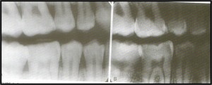
Decrease in kV-decrease in density-film appears lighter
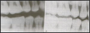
a) Silver amalgam, e) enamel, s) stainless steel crown, z) zinc oxide
CONTRAST
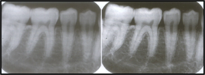
The difference in the degree of blackness (densities) between adjacent areas on a dental radiograph is termed Contrast.
GEOMETRIC CHARACTERISTIC
Three geometric characteristic of the radiographic image:
Sharpness
Magnification
Distortion
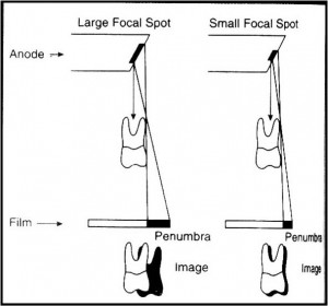
SHARPNESS
(Detail, Resolution, or Definition)
Refers to the capability of the x-ray film to reproduce the distinct outlines of an object, or smallest details of an object are reproduce on a dental radiograph.
Influencing factors:
Focal spot size
Film composition
Movement
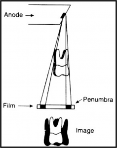
MAGNIFICATION
Image magnification refers to a radiographic image that appears larger than the actual size of the object it represents.
Results from the divergent paths of the x-ray beam.
Influencing factors
Target-film distance
Object film distance
DISTORTION:
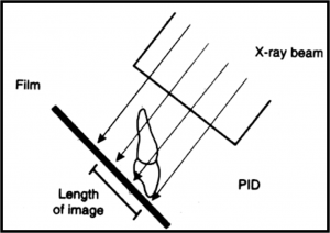
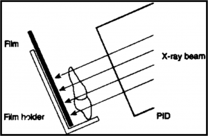
Dimensional distortion of a radiographic image is a variation in the true size and shape of the object being radiographed.
Influencing factors:
Object film alignment
X-ray beam alignment
 Â
An artifact is a structure or appearance that is not normally present in the radiograph and is produced by artificial means.
Various other factors also affect this, ranging from:
Armamentarium
Operator
Patient
Exposure
Processing
Storage
Handling
Artifact errors
PROBLEM: NO IMAGE
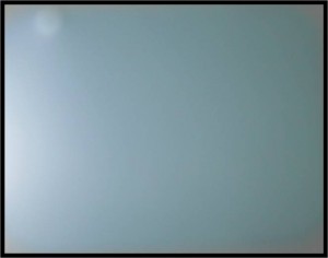
CAUSE: Film not exposed, failure to turn on x-ray machine,
electrical failure, or malfunction of the machine
ACTION: Check machine, ensure proper exposure of film,
Make sure that x-ray machine is on.
PROBLEM : LIGHT IMAGE
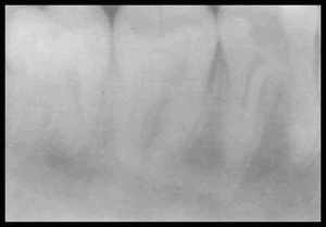
CAUSE: Incomplete exposure (failure to depress the exposure switch for the
entire time), faulty generator, not enough exposure (mA, kVp, time),
film exposed backwards.
ACTION: Check proper switch operation, check exposure factors and increase
if necessary,
PROBLEM : DARK IMAGE
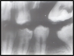
Cause: Faulty generator, too much exposure (mA, KVp, time), not enough distance,
Action: check exposure factors and decrease if necessary,
TECHNICAL ERRORS
PROBLEM : INCORRECT FILM PLACEMENT
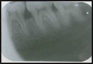
CAUSE: Failure to capture the entire crown of a tooth may be due to
improper film placement or beam alignment
ACTION: Correct film placement demonstrating the entire tooth,
including the apex and surrounding structures
PROBLEM: DROPPED FILM CORNER
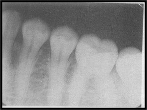
CAUSE: Dropped film corner is seen when the edge of the film is not
placed parallel to the incisal or occlusal surfaces of the teeth
ACTION: Make certain that edge of the film is placed parallel
to the incisal-occlusal surfaces of the teeth.
PROBLEM: ANGULATION PROBLEM
Angulation is a term used to describe the alignment of the central ray of the x-ray beam in the horizontal and vertical planes.
Horizontal angulation refers to the positioning of the PID in a horizontal or side-to-side planes.
Vertical angulation refers to the positioning of the PID in a vertical or up-and-down plane.
PROBLEM: OVERLAPPED PROXIMAL CONTACTS
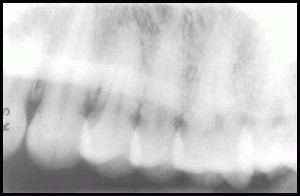
CAUSE: Due to inaccurate angulation
of the X-ray beam in a horizontal dimension
ACTION: Direct x-ray beam through the interproximal regions
PROBLEM: ELONGATED IMAGES
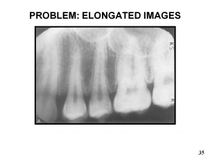
CAUSE: Roots of these teeth appear very long owing to a lack of
vertical angulation of the X-ray beam
ACTION: Use adequate vertical angulation with the bisecting technique
PROBLEM: FORESHORTENED IMAGES
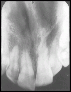
CAUSE: Very short roots are the result of excessive vertical angulation
ACTION: Do not use excessive vertical angulation with bisecting technique
PROBLEM : BLURRED IMAGE
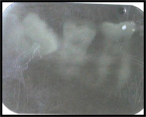
CAUSE : patient motion, film motion
ACTION : Give patient proper instructions not to move
PROBLEM: CONE-CUT
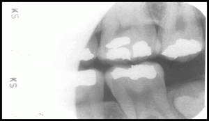
CAUSE:A partial image or cone cut is due to misalignment of the x-ray
beam over the entire film
ACTION: Make certain that the x-ray beam is centered over the film
and the entire film is covered by the diameter of the PID
PROBLEM: STRETCHED AND DISTORTED IMAGES
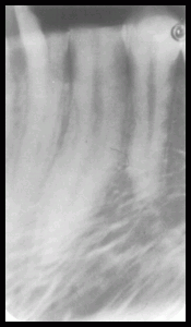
CAUSE: The disorted lower portion of this radiograph is due to the film bending
ACTION: Check film placement and pt’s finger pressure, instruct the pt to
stabilize gently
PROBLEM: THIN BLACK LINE
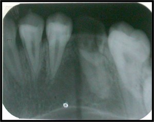
CAUSE: Film was creased and film emulsion cracked
ACTION: Do not bend film excessively
PROBLEM : DOUBLE IMAGE
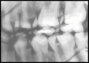
CAUSE: Double exposure, film movement during exposure
ACTION: Organize workspace and after each exposure place film in paper
cup to avoid exposed and unexposed films.
PROBLEM: MOVEMENT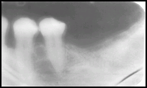
CAUSE: Movement on the part of the patient during exposure gives a
blurred image
.
ACTION: The patient should be monitored at all times during
radiographic procedure.
