PARALLEL GRIDS
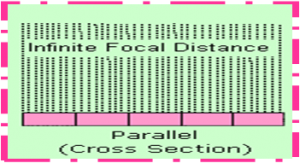
When strips are not progressively angulated but are perpendicular to the surface of the grid, the grid is termed “parallel” .
USED in fluroscopy & mobile imaging.

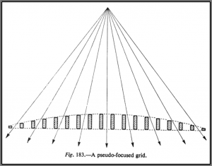
PSEUDO FOCUSSED GRIDS
This is constructed by reducing the height of strips progressively from centre to edge
Manufacturing is extremely difficult, as failure to achieve uniform grid pattern may mar the visual appearance and usefulness of radiograph

STATIONARY GRIDS.
WAFER GRIDS- matches the size of cassettes & is used by placing it on top of image receptor.
typically taped to the image receptor to prevent sliding during procedure.
GRID CASSETTE – image receptor that has a grid permanently mounted to its front surface.
GRID CAP – contains a permanently mounted grid & allows the image receptor to slide in behind it.
MOVING (Bucky) GRIDS
To remove the fine lines when wing stationary grids, one solution is to move the grid side ways across the film during the exposure, then the shadow of grid strips are blurred out
For lines to be effectively blurred out grid must move distance equal to 3-4 interspaces during the time of exposure
If not, there will be incomplete blurring of lines
The required minimum speed is determined by exposure time and no. of grid lines/cm
Moving grids were introduced by DR. POTTER in 1920 and since then many design of moving mechanism have been suggested and used mainly to overcome stoboscopic effect
The good average installation would have a grid movement and grid with the characteristics in the range of
– Ratio: 8-10
– Focussing Distance: 90 cms
– Movement: 0.6-1.2 cm either side of the of the
centre
– Lines/cm: 30-34
SINGLE STROKE:
– Spring is used to pull the grid at uniform speed
across film
– Speed of movement controlled by adjustable oil dash pot
– Overall movement is about 2.5 cms for about
0.2 to 1.5 seconds
DISADVANTAGE:
– This has to be set manually before each exposure
OSCILLATING AND RECIPROCATING MOVEMENTS
Here the necessity of resetting the grid before every exposure is avoided as the grid is always moving at sufficiently high speed
The grid moves to and fro across the film repeatedly during exposure
DISADVANTAGE:
There is space of 5 cms required between patient and film to accommodate the movement thus causing magnification and geometric unsharpness
GRID CHARECTERISTICS
Some of the relevant characters have to be taken into consideration in the design of the grid.
Number of strips of lead per cm (N)
The total no. of strips will vary from a few 100 – 1000 or more.
Greater the no. N ,the less will be the grid lines on the film visible.
But it is also imp That no. must be same over the whole film , & the lines must be straight & parallel.
A uniform, yet more coarse pattern (smaller value of N) is less visible than a fine (larger value N )but non uniform pattern.
Commonly used grids have b/w 20- 28 lines per cm
Good grids may have 40 lines per cm.
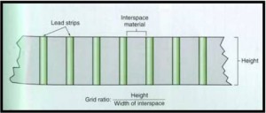
GRID RATIO
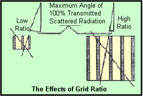
It is seen that higher the ratio greater the restriction in volume for the scattered radiatn can reach the film.
Therefore higher ratio is desirable.


Usually value of about 5-8 to 10-12 are used and in high Kv work grids with ratio of 16 is also used
Grids are manufactured with the following ratios as standard:
– Parallel and Focused N30 r 6, 8, 10
– Parallel and Focused N40 r 6, 8, 10, 12
– Parallel and Focused N70 r 6, 8, 10, 12, 16
– Other ratios can be manufactured on special
request
LEAD CONTENT (p)
Removal of scattered radiatn is as imp as transmission of primary beam transmission.
Other than the ratio of the grid affecting the efficiency of grid,
selectivity of grid- transmitted primary radiation
transmitted scatter radiation
An efficient grid should have high selectivity
Various works have shown that actual lead content/unit area (measured as gm/cm2) is determining factor for efficiency of grid
Actual lead content per unit area (measured as g per cm2 )is a determining factor for the efficiency.
LEAD CONTENT
A heavy grid i.e. with lot of lead per sq mm2 is more efficient than a lighter one.
Values usually range from 0.2 per cm2 – 0.9 g per cm2.
For 2 grids with same ratio the heavier one will remove greater amount of scatter than the lighter one
Further more heavier grid of lower ratio can be a better than a lighter grid of higher ratio.
Grid factorÂ
IT represents the extent to which the x ray tube exposure must be increased to compensate for the primary & scattered radiation reaching the film.
Grid Factor = Exposure (m As) with a grid
Exposure without a grid
Typical values range from 2-6.
FOCAL RANGE
:
Focal range is the distance interval in which an X-ray tube can be used with a certain grid.
With lower ratio grids, the focal range is considerably wider, with a higher ratio, the range is narrower